


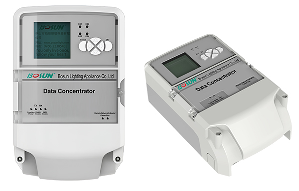
Features
·LCD display
·High-performance 32-bit ARM9 MCU
·Embedded Linux OS platform
·With 10/100M Ethernet interface RS485 interface, USB interface
·Support GPRS/4G and Ethernet communication mode
·Firmware upgrading: online, cable and local USB disk
·Built-in smart meter: remotely data reading (including external meter)
·Built-in PLC communication module
·Built-in 4 DO、8 DI(6DCIN+2AC IN)
·Built-in RTC, support local scheduled task
·Optional configuration: GPS
·Fully sealed enclosure: anti-interference, withstand high voltage,lightning andhigh frequency signal interference
Communication module replaceable:
BOSUN-SL8200C with PLC | BOSUN-SL8200CZ with ZigBee | BOSUN-SL8200CT with RS485 | BOSUN-SL8200CLR with LoRa-MESH
Scope:
-Public lighting, Remote distribution box switch control, Remote control of lamps,Remote monitoring electrical data
-Tunnel lighting, Street lighting, Landscape lighting, Energy Monitoring
Precautions
Please read this specification carefully before use, so as to avoid anyinstallation error that might cause the malfunction of the device.
Transportation and storage conditions:
(1) Storage Temperature:-40°C~+85°C;
(2) Storage Environment:avoid any humid, wet env;
(3) Transport: avoid falling;
(4) Stockpiling: avoid over-piling;
Notice
(1) On-site installation should bebyprofessional personnel
(2) Do not install the device in a long-termhigh temperature environment, which mightshorten its lifetime
(3) Well insulate the connects during theinstallation
(4) Wire the device STRICTLY according tothe attached diagram, inappropriate wiringmight cause deadly damage to the device
(5) Add a 3P air switch to the front of the ACinput in order to ensure safety
(6) Install the antenna(if have) out of thecabinet for better wireless signal
Parameters
| Basic Info | |||||
| Ac input | Min | Typical | Max | Unit | Note |
| Voltage | 96 | 220 | 500 | VAC | Single phase orthree phasespower supply |
| Frequency | 47 | 50 | 63 | Hz | |
| Power | 2.0 | 3.0 | 5.0 | W | |
| Hardware Platform | |||||
| Items | Features | ||||
CPU kernel | ARM9 kernel,32-bit RISC structure processor. | ||||
| Built-in RTC | Adjusted circuit via high precision meter; Low consumptioncurrent; Built-in temperature compensation; Backup battery | ||||
| Built-in PLC module | Fonda-developed protocol for PLC solution, professional andreliable. | ||||
| Built-in RS485 module | Support various external devices | ||||
| Built-in GPS module | Auto locate the device, support several GNSS types(Optional). | ||||
| LCD display | DS160*160 LCD display, showing all needed information | ||||
| Built-in USB port | High speed 2.0 USB port, support local upgrading and specific devices. | ||||
| Power control | Low cost, wide input range, high dynamic response, highefficiency, high stability and low ripple. | ||||
| Power control system | Low cost, wide input range, high dynamic response, highefficiency, high stability and low ripple. | ||||
| Built-in meter | High precision electrical parameter detection circuit, support three- phase voltage and current; record active power, reactivepower, electric energy etc; | ||||
| Battery management | Built-in 12V battery charge and discharge circuit management, stable and reliable | ||||
| Software Control Platform | |||||
| Embedded OS | Embedded Linux OS, reliable and easy to use. | ||||
| Task management | Multiple task strategy management: LCU management, task management, data storage management, scheduled taskexecution, etc | ||||
Safety Performance Index
| Terminal Clearance& Creepage Distance | |||
| Rated Voltage V | Electrical Clearance(mm) | Creepage Distance(mm) | |
| U<25 | 1 | 1.5 | |
| 25 | 2 | 2 | |
| 60 | 3 | 4 | |
| 250 | 4 | 5 | |
| Insulation Resistance | |||
| Insulation resistance of each electrical circuit to the ground and between eachelectric circuits: | |||
| Rated insulation voltage(V) | Insulation resistance Requirement(M Ω) | Test Voltage(V) | |
| Normal condition | Damp & heat condition | ||
| U≤60 | ≥10 | ≥2 | 250 |
| 60 | ≥10 | ≥2 | 500 |
| U>250 | ≥10 | ≥2 | 1000 |
| Insulation Strength | |||
| Insulation strength test for all the circuits of concentrator, under the condition of50Hz AC input, in 1 minute, there is no breakdown, flash-over or more than 5mAleakage current. | |||
| Rated insulation voltage(V) | Effective value of test voltage(V) | Rated insulation voltage(V) | Effective value of test voltage(V) |
| U≤60 | 500 | 125 | 2000 |
| 60 | 1500 | 250 | 2500 |
| Impulse Withstand Voltage | |||
| Insulation strength test for all the circuits of concentrator, under the condition of50Hz AC input, in 1 minute, there is no breakdown, flash-over or more than 5mAleakage current. | |||
| Rated insulation voltage(V) | Effective value of test voltage(V) | Rated insulation voltage(V) | Effective value of test voltage(V) |
| U<60 | 2000 | 125 | 5000 |
| 60 | 5000 | 250 | 6000 |
Basic Functions
| Control Interface Specification | ||||||
| Function | Channels | Note | ||||
| DO (Relay output) | 4- route | Stem node output,Contact capacity: 250VAC/5A; public ACLend | ||||
DIinput | 2- route | AC input, public ACN end | ||||
| Dl (on-off input) | 6- route | Stem node input,public DICOM end | ||||
| Voltage detection | 3- route | Detect phase voltage and line voltage of three-phase | ||||
| Current detection | 3- route | Detect phase current and line current of three-phasevia a current transformer; | ||||
| Leakage detection | 1- route | Detect leakage current via a zero sequence current transformer | ||||
| Battery charging interface | 1- route | Provide output to charge a 12V battery, withover-charge and over-discharge protection. | ||||
| DC output | 1- route | Provide 1-route 13.5V/200mA power supply for external use. | ||||
| Remote communication module | 1 pcs | Support multiple types of GPRS module(GPRS/CDMA); | ||||
| RS485 communication interface | 1- route | Read and control external devices that support RS485 protocol. | ||||
| Ethernet communication interface | 1 pcs | Support local communication, support Ethernetinterface communication; | ||||
| USB interface | 1 pcs | Support USB disk upgrading | ||||
| PLC Communication Performance | ||||||
| Parameter | Min | Typical | Max | Unit | Remarks | |
| Modulation method | BPSK | |||||
| Frequency | 132 | KHz | ||||
| Speed | 5500 | bps | ||||
| Sensitivity | -80 | -60 | dBV | 0dBV=2.82Vpp | ||
| Communication method | Support three-phase four-line AC power line communication | |||||
| Data Statistics Description | ||||||
| Parameter | Description | Discre-pancy | Resolution | |||
| Input Voltage specification | Three phase four line | |||||
| Input Current specification | 5A configuration, input range 0 to6A, threshold 5 mA | |||||
| Data accuracy | <3% | |||||
| Voltage accuracy | Three-phase phase voltage andline voltage | ±0.5% | 0.01V | |||
| Current accuracy | Three-phase phase current andline current | ±0.5% | 0.001A | |||
| Power calculation | Active power calculation | Single-phase total active power calculation, three-phase total active power calculation | ±0.5% | 0.001KW | ||
| Reactive power calculation | Single-phase total reactive power calculation, three-phase total reactive power calculation | ±0.5% | 0.001KVar | |||
| Apparent power calculation | Single-phase apparent powercalculation, three-phase apparent power calculation | ±0.5% | 0.001KVA | |||
| Electrical energy statistics | Active power statistics | The total active power statistics single-phase total active power statistics | ±1% | 0.01KWH | ||
| Reactive power statistics | The total reactive power statistics,single-phase total reactive power statistics | ±1% | 0.01KVarH | |||
| Power factor | Three-phase power factor calculation | ±0.5% | 0.001 | |||
| Frequency | Three-phase frequency calculation | ±0.01% | 0.01Hz | |||
| Parameter Function Control Table | ||||||
| Model | Communication method | Communication parameters | ||||
| SL8200C | PLC | PLC transmission;Frequency 132Khz;Speed 5.5 Kbps | ||||
| SL8200CZ | Zigbee | Zigbee transmission,automesh, node to node distance within 150m maximum 16 hops; Frequency: 2.4Ghz-2.485Ghzdivided into 16 Channels;Speed: 250Kbps | ||||
| SL8200CLR | LoRa-MESH | Model | SL8200CLR-C1 | SL8200CLR-C | SL8200CLR-E | SL8200CLR-A |
| Communication point | 433M | 470M | 868M | 915M | ||
| Frequency point quantity | 3 | 10 | ||||
| Frequency Range | 433 1135M 433 6375M | 485 5M 495 5M | / | |||
| Communication standard | IEEE 802.15.4g | |||||
| Routing | Custom routing node, one data routing | |||||
| All Centralized Controller is carried RS485 | ||||||
EMC Index
| ESD Immunity | |||||
| In normal operating status, the concentrator is able to withstand 8KV direct or indirect electrostatic discharge from manual operation or other surrounding devices. | |||||
| Voltage Dip and Interruption Immunity | |||||
| In a voltage dip or short-time interruption incident, the concentrator will not behalted, wrong-action or damaged, and back to normal when power supply recovers | |||||
| Power Frequency Magnetic Field Immunity | |||||
| The concentrator can work under the power frequency magnetic field of 50Hz,400A/m. | |||||
| Radiated Electromagnetic Field Immunity | |||||
| The concentrator can withstand the extra radiated electromagnetic field immunityof 10V/m. | |||||
| Electrical Fast Transient Immunity | |||||
| The concentrator can withstand the electrical fast transient as below (excluding PLC) | |||||
| Testing item | Level | Testing value | Testing circuit | ||
| Electrical fast transient | 2 | 2.0kV(Coupling) | Communication line | ||
| 3 | 1.0kV | Status signal input | |||
| 4 | 2.0kV | AC input | |||
| 4 | 4.0kV | Power circuit | |||
| High Frequency Oscillatory Wave Immunity | |||||
| The concentrator can withstand the high frequency oscillatory wave 1MHz as below: | |||||
| Testing item | Level | Testing value | Testing circuit | ||
| High frequency oscillatory wave | 2 | 1.0kV (common mode) | AC input, Statussignal input | ||
| 4 | 2.5kV (common mode) 1.25kV (differential mode) | Power circuit | |||
| Surge lmmunity | |||||
| The concentrator can withstand the surge as below: | |||||
| Testing item | Level | Testing value | Testing circuit | ||
| Surge | 2 | 1.0kV(common mode) | Status signal input | ||
| 3 | 2.0kV(common mode) | ||||
| 4 | 4.0kV(common mode) 2.0kV(differential mode) | Power circuit | |||
| Power circuit | |||||
| Parameter | Min | Typical | Max | Unit | Remarks |
| Working temperature | -40 | 25 | 85 | °C | Excluding GPRS module |
| Relative humidity | 5 | 95 | % | Status without condensation | |
| Barometric pressure | 66 | 108 | kPa | BB2 level | |
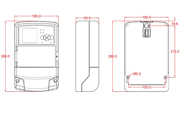
| Size(L*W*H) | 288*177*95 | mm | |||
| Weight | 2080 | g | |||
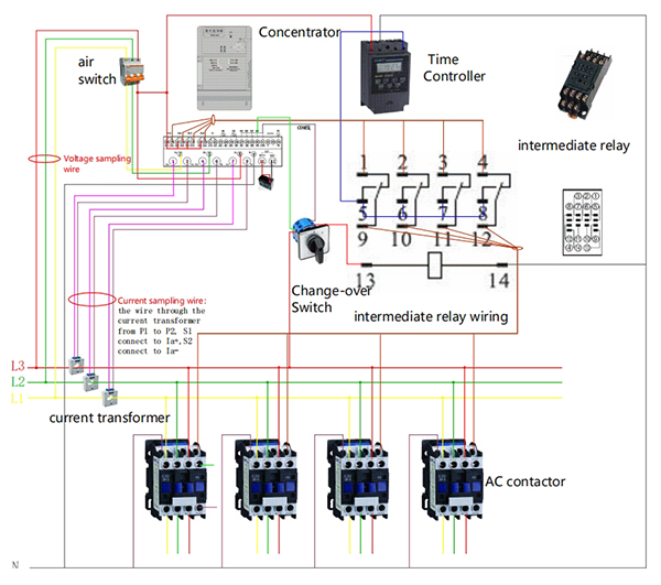
Wiring Diagram

Notice:
1-Ua, Ub, Uc are for AC input, N for null line;
2-la, lb, lc are for the current detecting input, they cannot be directly connected toAC ,and must install an AC transformer;
3-la, Ib, Ic must be STRICTLY connected to phase A/B/C ac input;
4-DO1-DO4 is for digital output to control the AC contactor;
5-A converter is needed to control 380V AC contactor, the common port is AC-IN, connecting to AC live line
6-lz is for leakage detection, need to connect to an external zero sequence current transformer to detect leakage current.
7-DI1-Dl6 is for digital input, the common port is DI COM, it cannot be connected to AC/DC current or voltage.
8-AC DI1,AC DI2 are for AC detection input, the common port is AC N, it cannot be connected to DC current or voltage.
9-12V+,GND are for external battery, positive and negative points must not be correct;
10-13.5V+,GND is for external power supply connection, providing DC 13.5V/200mA.
11-Please connect “+” “-” correctly, and make sure the external device current is no more than 200mA.